The exact determination of contact stresses for complicated surfaces is a difficult process. It depends strongly on the geometry of the contacting surfaces. Point/line contacts are used to describe ideal situations whereby the contacting bodies do not undergo any deformation, that is, theoretically;
- For 2 spheres pressed against each other, the contact surface is a point
- For 2 parallel cylinders pressed against each other, the contact surface is a line
However in practice, a real area of contact is formed due to the immediate deformation of the mating surfaces. Thus, when two bodies having curved surfaces are pressed together, the point or line contact changes to area contact, and the stresses developed in the two bodies are three dimensional. The size of the contact area depends on the load and the materials from which the objects which are in contact are made of. The deformation is elastic in general, although some plastic deformation is also possible. These stresses were first studied by the German physicist Heinrich Hertz in 1881.
Hertz’s analysis of contact stress involves the following set of assumptions:
- The surfaces are smooth and frictionless.
- The contact area is small compared to the size of the bodies.
- The bodies are isotropic and elastic.
The preliminary steps towards the solution to contact problems basically entail determining the size and shape of the contact area, the normal pressure distribution, resulting stresses and eventually the deformations. The common classical solutions employed in elastic contact problems are illustrated below.
1. Spherical contact
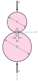
Suppose two spheres are pressed against each other with a collinear pair of forces F (Figure 1).
The contact surface is ideally a point. However, from a practical standpoint, the area of contact is circular in shape, with its radius given by the following equation, where E and v are the elastic constants:
The normal pressure distribution within the contact area is hemispherical as shown in Figure 1.The maximum contact pressure, which is also the maximum principal stress, occurs at the centre of the contact area and is given by:
The principal stresses occur on the z-axis and can be determined from the following equations:
Equation 3: \( \sigma_x = \sigma_y = -P_{max} \Bigg[ 1 – {\left| \frac{z}{a} \right|}\taninv{\frac{1}{z/a} } \Bigg] \)
The maximum shear stress in any of the two spheres can be determined from:
The relative displacement of the centres of the spheres (deformation or more precisely indentation) due to the contact force is given by:
1.1. Contact between a sphere and a surface
Equations 1, 2 and 6 are perfectly general. They can be employed for determining the contact area and the contact pressure respectively for two scenarios; one scenario entailing a sphere pressed against a flat surface and the other, involving a sphere pressed against an internal spherical surface.
For a plane surface, the radius of curvature = ∞, and by extension, the diameter = ∞.
For an internal surface, the radius of curvature ∞, and by extension, the diameter < 0.
The corresponding parameters (a, Pmax and ∂) can be determined by substituting the above conditions in Equations 1, 2 and 6.
2. Cylindrical contact
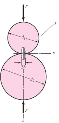
When two cylinders are pressed against each other (Figure 2) with a collinear pair of forces F, a rectangular area of contact, of width b and length l, is formed. Theoretically, this contact surface is supposed to be a line.
The half width of the rectangular area is given by:
The pressure distribution is elliptical and the maximum contact stress can be determined from:
For a special case, with similar elastic constants for both cylinders, i.e. v1=v2=v and E1=E2=E, the deformation caused by the contact force can be determined from:
The principal stresses on the z-axis can be determined using the following equations:
Another contact case entails friction that causes shear stresses on the contact zone. These elevated stresses are beyond the Hertzian field.
2.1 Contact between a cylinder and a surface
Equations 7 and 8 can be used to determine the contact parameters between a cylinder and an internal spherical surface or a flat surface. The aforementioned conventions pertaining to the diameters in 1.1 must be used.
3. Two curved surfaces
For surfaces with a minimum and maximum radius of curvature, the contact pressure may be determined using:
Where a and b are the lengths of the semi-axes of the elliptical area of contact
The angle between the normal planes in which the minimum radii of the contacting surfaces lie, dictates the values of a and b.

